References
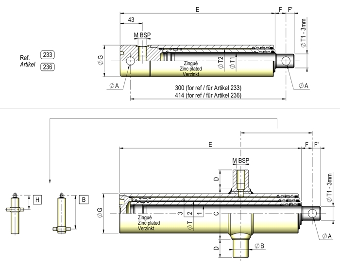
| Reference | ØA | ØB |
Z Course Stroke Hub |
H | I | B | ØT1 | ØT2 | ØT3 | ØT4 | ØT5 | ØT6 | ØT7 |
Nombre de sections Number of sections Anzahl elemente |
A |
A Poussée Thrust Schub |
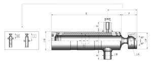
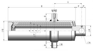
B | C | D | D max | E | F | F' | F min | G | H | HT min | I | J | K | L | M | N | O | P | T | X | X min | Y | Max* | Vol. (Ltr) | Vol. (cm3) |
Pression Pressure Druck (bar) |
Vérin Cylinder Zylinder |
Débit Flow Leistung (vol) |
Débit Flow Leistung (Ltr min) |
Poids Weight Gewicht (Kg) |
Pression max Max pressure Max druck |
Débit max Max flow Max leistung |
Rapport de pilotage Pilot ratio Aufsteuerung |
OPTION Berceau Cradle Ring N° |
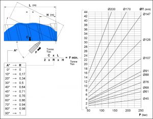
Capacité réelle de levage du vérin à 200 bars (Tonnes) |
Longueur Length Länge (m) |
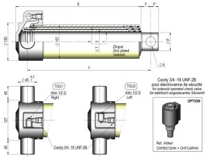
pressostat |
Téléchargement Download |
||
|---|---|---|---|---|---|---|---|---|---|---|---|---|---|---|---|---|---|---|---|---|---|---|---|---|---|---|---|---|---|---|---|---|---|---|---|---|---|---|---|---|---|---|---|---|---|---|---|---|---|---|---|---|---|---|---|---|---|
| 233 | 300 | 30 | 45 | 16.2 | 299 | 21 | 16 | 61 | 3/8 | 0.43 | 7.4 |

|
|||||||||||||||||||||||||||||||||||||||||||||
| 236 | 517 | 30 | 45 | 16.2 | 413 | 21 | 16 | 61 | 3/8 | 0.73 | 8 |
|
|||||||||||||||||||||||||||||||||||||||||||||
| 235 | 517 | 135 | 30 | 45 | 16.2 | 30 | 85 | 35 | 352 | 21 | 16 | 61 | 3/8 | 0.73 | 7.4 |
|
|||||||||||||||||||||||||||||||||||||||||
| 337 | 761 | 138 | 30 | 45 | 61 | 16.2 | 30 | 98 | 35 | 351 | 21 | 16 | 76 | 3/8 | 1.56 | 11 |
|
||||||||||||||||||||||||||||||||||||||||
| 339 | 940 | 393 | 30 | 45 | 61 | 16.2 | 30 | 98 | 35 | 412 | 21 | 16 | 76 | 3/8 | 1.9 | 12.7 |
|
||||||||||||||||||||||||||||||||||||||||
| 294 | 390 | 100 | 283 | 45 | 61 | 26 | 25 | 98 | 25 | 293 | 30 | 25 | 80 | M16x1.5 | 1 | 10.4 | 00 |
|
|||||||||||||||||||||||||||||||||||||||
| 295 | 500 | 100 | 338 | 45 | 61 | 26 | 25 | 98 | 25 | 348 | 30 | 25 | 80 | M16x1.5 | 1.3 | 12.3 | 00 |
|
|||||||||||||||||||||||||||||||||||||||
| 296 | 620 | 107 | 399 | 45 | 61 | 26 | 40 | 100 | 40 | 409 | 30 | 25 | 80 | 1/2 | 1.6 | 15.1 | 0. |
|
|||||||||||||||||||||||||||||||||||||||
| 297 | 700 | 100 | 439 | 45 | 61 | 26 | 40 | 100 | 40 | 449 | 30 | 25 | 80 | 1/2 | 2 | 16.3 | 0. |
|
|||||||||||||||||||||||||||||||||||||||
| 298 | 820 | 107 | 499 | 45 | 61 | 26 | 40 | 100 | 40 | 509 | 30 | 25 | 80 | 1/2 | 2.1 | 18.2 | 0. |
|
|||||||||||||||||||||||||||||||||||||||
| 306 | 910 | 110 | 399 | 45 | 61 | 76 | 26 | 45 | 115 | 45 | 409 | 30 | 25 | 95 | 1/2 | 3.1 | 20.8 | 1 |
|
||||||||||||||||||||||||||||||||||||||
| 201 | 595 | 107 | 396 | 61 | 76 | 31 | 45 | 115 | 45 | 406 | 30 | 25 | 95 | 1/2 | 2.5 | 23 | 1 |
|
|||||||||||||||||||||||||||||||||||||||
| 202 | 795 | 107 | 496 | 61 | 76 | 26 | 45 | 115 | 45 | 506 | 30 | 25 | 95 | 1/2 | 3.3 | 26 | 1 |
|
Features
The study, the conception and the technical
specifications are only suitable for tippers.
– Max pressure : 200 bars
– Proof pressure : 300 bars
– Maximum speed : 0.2m/s
– Temperature : – 30°C to + 90°C
– Hydraulic mineral oil
• Materials
– Seamless tube NFA 49311/312 tube machined,
ground, treated and polished Ra<0.4μ
– Cold-drawn tube
– Round bar Steel C35R, machined, ground and
polished Ra<0.4μ
– Each component is nitrited (except cylinder
bottom)
• Seals
– Rod: compact polyurethane lip seal + 1 polyurethane wiper seal
– Cylinder bottom: O RING 80 shore + back up
ring or static seal
• Marking
On the tube or bottom: REFERENCE + CH +
WEEK/YEAR of manufacture
• Testing by “pick up”
Recommendations
– Protect the hydraulic circuit by a relief valve and a filter
– Check the state of purity of the fluid (foreign bodies);
– Remember to purge the cylinders and the hydraulic circuit;
– Do not weld onto the cylinder;
– Do not, under any circumstances, use the tipping system as a mechanical stop;
– Never allow the body to lean against the cylinder when in stowed position (gap > 20mm).
• Storage:
– The cylinder rod must be greased before being stored;
– Protect the cylinder shaft and trunnions during high pressure steam cleaning.
• Spare parts: joint pockets, see price list.
• Instructions: on request.
• Guarantee: please refer to the general sales conditions.
The normal operation of a CHAPEL telescopic cylinder consists in the regular lifting of a tipper body to progressively empty its load over its path, whilst respecting the operating and safety conditions.
A tipping system is solely a lifting device, it cannot, under any circumstances, stabilise or guide the tipper body.
On choosing a cylinder, the weight C is equal to the weight of the body added to the weight ofthe load.
Additional information
SAFETY PROCEDURES TIPPING
Plan a gap from 20 to 30mm
Ensure that:
– The necessary tipping pressure is less than
the maximum recommended operating pressure;
– The load is compatible with the vehicle;
– The ground is stable and flat;
– There are no people or obstacles in the working
perimeter (at ground level and high up),
– The load has been distributed uniformly;
– The tyre pressure is correct;
– The load is progressively emptied.
PAY ATTENTION to loads sticking in the body
(wet earth, etc…)
Strong adhesion to the body may cause the
vehicle to tip over.
THE FOLLOWING IS STRICTLY PROHIBITED:
– Do not move the vehicle during tipping;
– Rapid operation of the cylinder tipper control;
– Working under a raised tipper body that has
not been secured;
– Tipping if the wind is buffeting the vehicle.
«Not following the above safety procedures
may cause considerable over-pressures and
transverse forces that are not allowed by the
cylinder.
This may therefore cause considerable damage
and place the operator in danger.»